
Bidirectional DC–DC Supercapacitor Energy Management System
August 2025 – February 2026
When a robot accelerates sharply or climbs a ramp, its chassis can briefly draw more power than the main supply can deliver. I reproduced and adapted an open-source design for our university’s RoboMaster team. The bidirectional DC–DC system charges a supercapacitor bank when demand is low and discharges it when the chassis needs extra power.
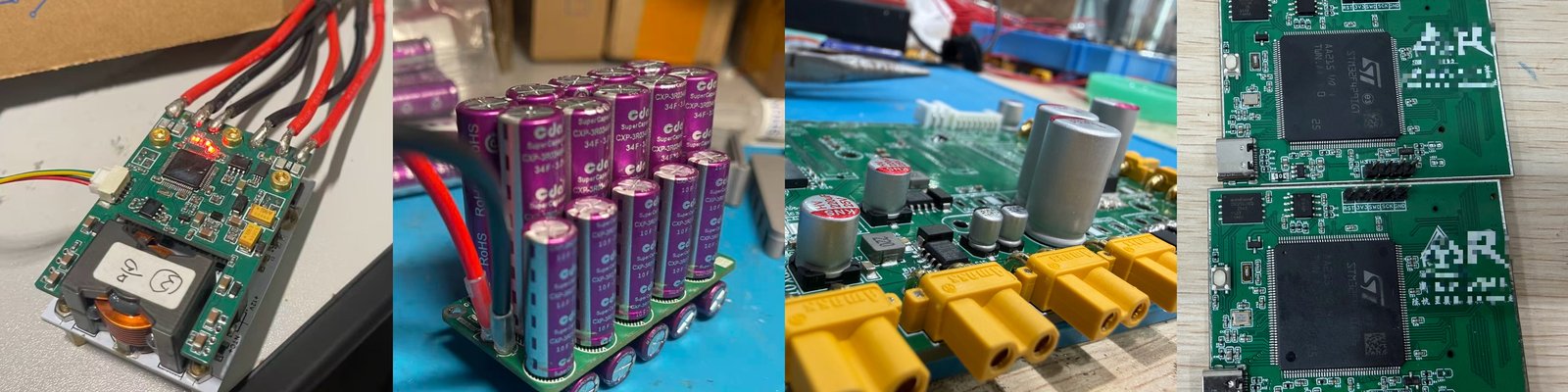
I used a four-switch buck–boost converter with an STM32F334 microcontroller. Synchronized ADC sampling and incremental PID control regulate power, current, and voltage. The hardware combines a six-layer PCB with an aluminum-core board and includes overvoltage and short-circuit protection. Because the voltage can divide unevenly across series-connected cells during charging, I used passive balancing to limit the voltage across each cell in the 44 F bank. The system stores approximately 1,980 J and operated without a fault during competition.
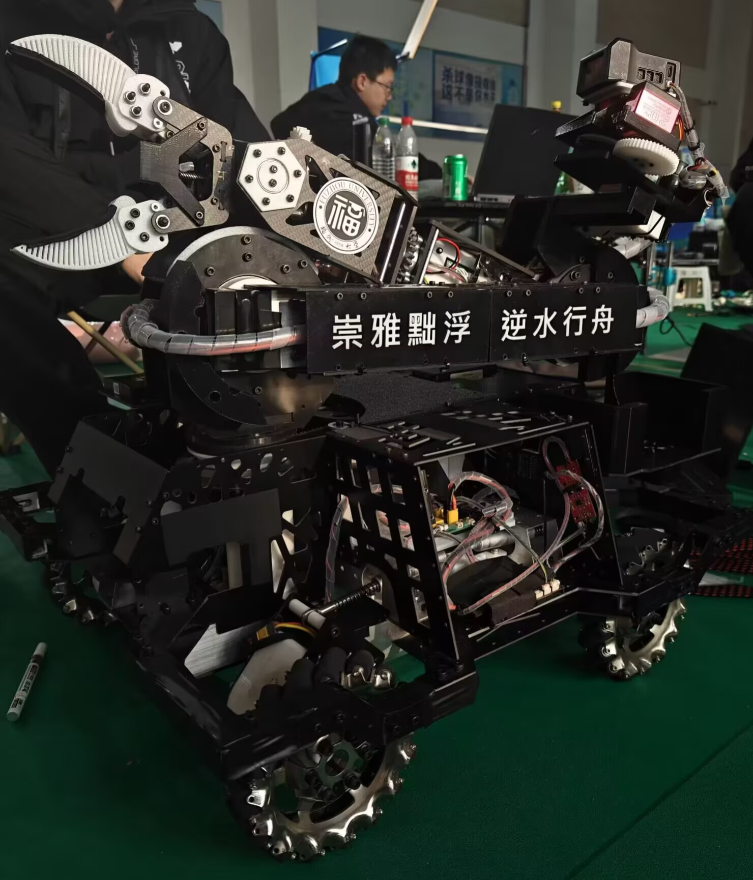
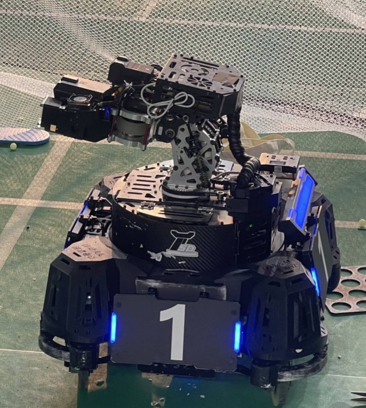
I was responsible for developing all the hardware circuits and routing the wiring on the Hero robot (Figure 3). I initially expected the wiring to be straightforward. Routing it through the whole robot showed me how much care it takes. Under the demands of a RoboMaster match, safe circuits and reliable connections are essential to keeping the robot running.