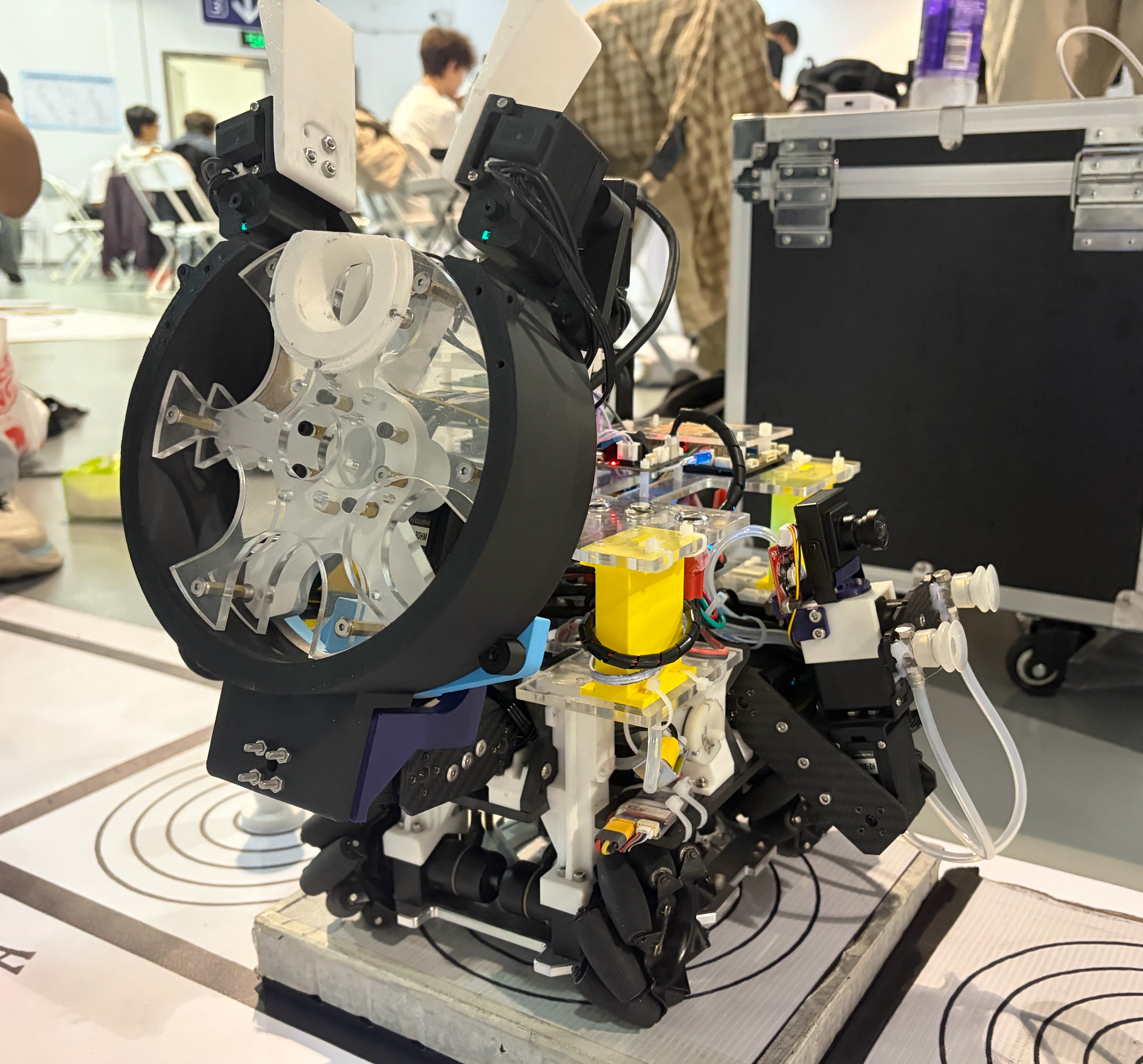
China Robot Competition – Intelligent Material Handling Robot
2026 · Fuzhou University · National First Prize, Vehicle-Based Intelligent Material Handling
My teammates and I built an autonomous robot for a simulated sports meet. It had to sort randomly arranged objects by color, deliver them to designated areas, and stack objects of the same color but different shapes. It also had to place first-, second-, and third-place trophies on podiums of different heights. Both tasks required the robot to navigate to each target and align itself accurately for pickup and placement.
How the robot handles objects
We used two STM32 microcontrollers, one for task scheduling and one for chassis motion control. The mecanum-wheel chassis follows straight lines and circular arcs using position feedback from the OPS module. During trophy collection, a Raspberry Pi running OpenCV recognizes the Chinese characters for first, second, and third place. A servo inside the carousel sorts the trophies while the robot follows an arc, so it can keep moving throughout collection.
For the stacking task, OpenCV identifies each object’s color and uses edge angles to distinguish cones from rectangular blocks. The main controller tracks each object’s position on the carousel, and a suction arm picks up the blocks. Once OPS brings the robot to the drop-off point, the vision system locates the center of the target circle so the chassis can fine-tune its position. The carousel selects the matching object, and the valve closes to release the block and complete the stack.
My hardware work
I led the team and was responsible for the hardware. I designed and soldered two PCBs: an STM32F429IGT6 core board and an expansion board that combines input protection, three step-down power rails, and the robot’s peripheral interfaces.
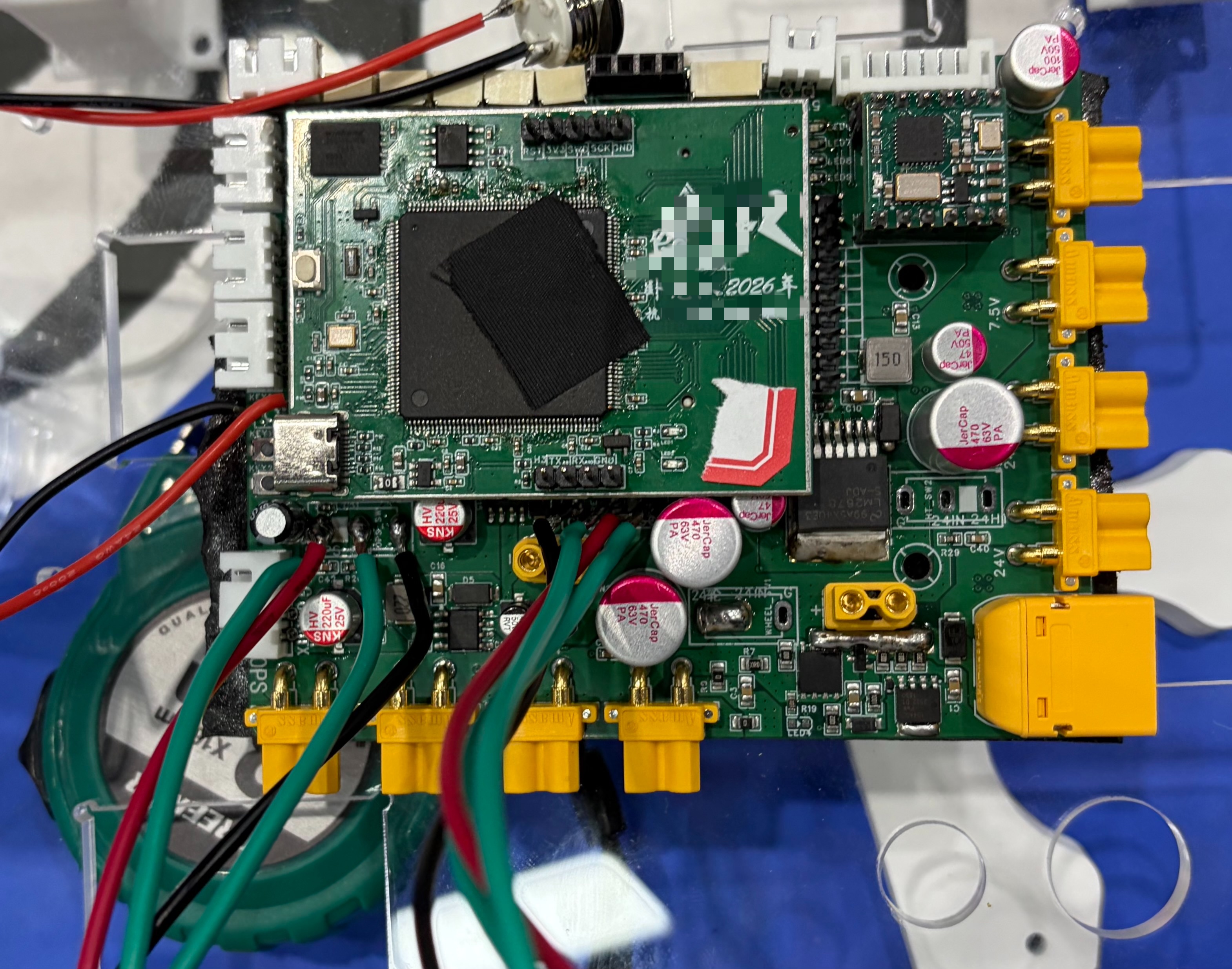
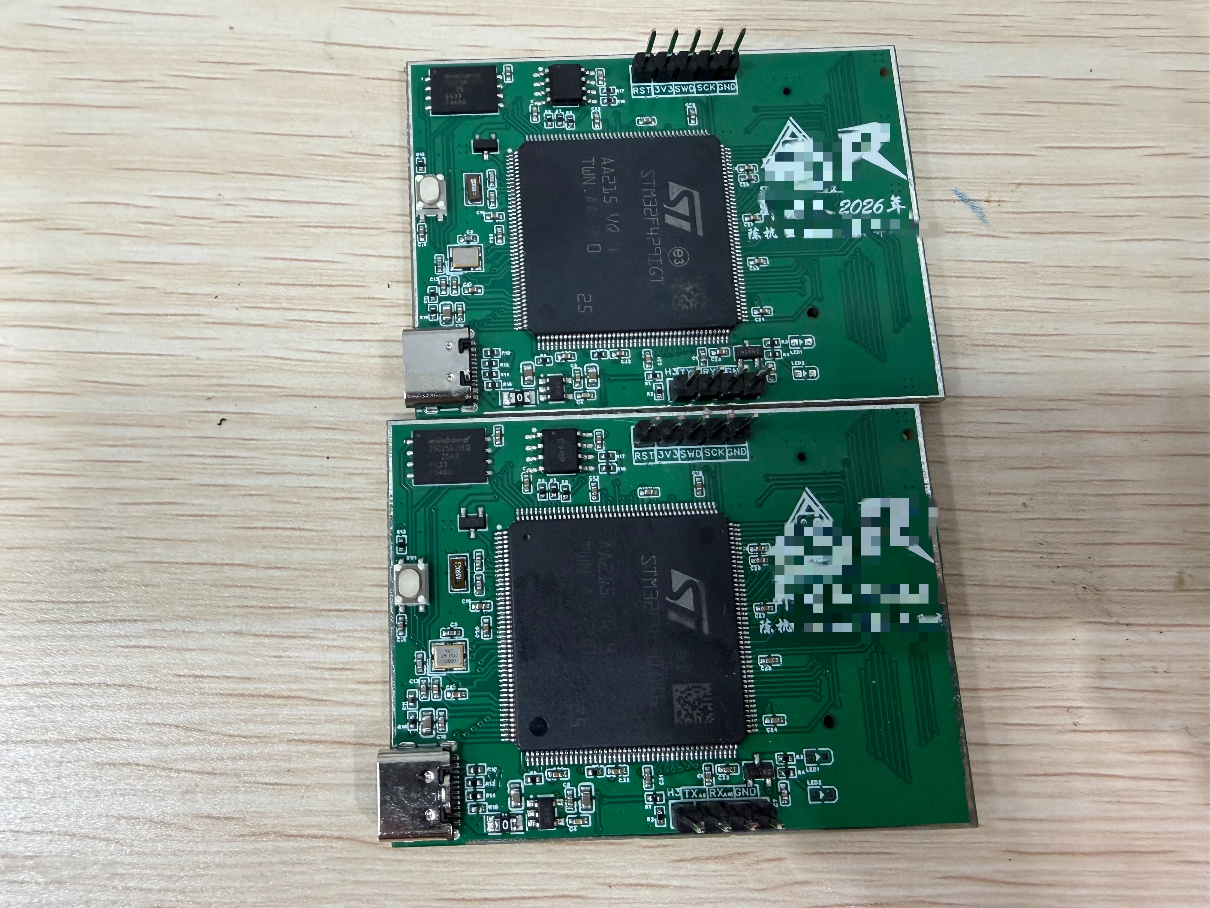
STM32F429 core board
I designed the core board as a compact, four-layer, 60 mm × 45 mm PCB suitable for batch production. A CAT6219 converts 5 V to 3.3 V for the STM32F429IGT6 and its logic devices. The board includes a crystal oscillator circuit, an AT24C02 EEPROM, and 32 MB of SPI flash. USB-C provides standalone power, SWD supports debugging, and a board-to-board connector mates the core board to the expansion board.
Power and peripheral board
I consolidated power distribution, input protection, and peripheral interfaces on a four-layer, 100 mm × 80 mm PCB. The 24 V input feeds the chassis directly. One LM2678 and two TPS5430 converters provide three step-down rails: 12 V for the air pump and servo controller, 5 V for the main controller and other logic, and a dedicated 5 V rail with electrostatic discharge protection for the OPS positioning module.
The power input includes transient voltage suppression, reverse-polarity protection, and a soft-start circuit. Separate switches let me power the chassis, core board, and OPS module individually during debugging. The expansion board provides connections for the Raspberry Pi, servo controller, code scanner, and auxiliary light. A MAX3232 translates between the OPS module’s RS-232 interface and the STM32 serial port. A TB6612 dual H-bridge switches the pump and solenoid valve.